Client
Pyxalis is a high performance CMOS image sensors supplier serving a wide range of applications from niche to high volume markets. Funded in August 2010, the company is located in Moirans, in the Grenoble French Alps.
Pyxalis designs and manufactures custom sensors but also made available to the market a range of high performance semi-custom platforms, amongst which HDPYX and this approach makes Pyxalis unique in the spectrum of European Image sensor design houses.
Project
The HDPYX sensor, developed by PYXALIS, is a 3MP, 120dB linear Dynamic range sensor, dedicated to metrology, scientific imaging, high-end security…
It features a flexible shutter operation (Rolling, Global, Global low noise) using an HDR 10um pixel and dedicated and patented sensor architecture. The Sensor embeds two High Dynamic range methods to reach 120dB Dynamic range intrascene, with HDR reconstruction on-chip. The sensor is also capable of acquiring low light levels with a noise floor measured down to 1.95e- RMS.
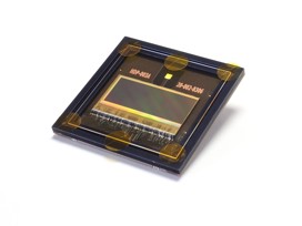
Figure 1: HDPYX sensor
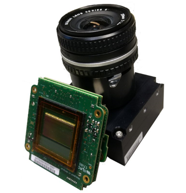
DELTATEC has been selected to design the demonstration camera, integrating the HDPYX sensor, to be used as a demonstrator or as an evaluation kit for PYXALIS customers. The system includes the electronic and the mechanical parts of the camera as well as a PC software package that includes a software development kit (SDK) and a graphical user interface (GUI) application that interact with the camera. It must be noticed that a few Pyxalis’s customers will use this camera as a product for low volumes applications (few hundred of units/year max).
Challenge(s)
The camera has to handle several imaging modes. In the most demanding configuration, the camera is able to capture from the sensor and transmit to the computer 3 Gbps of data. As an example, this represents a frame rate of 60 Hz for a resolution of 2808 x 1096 pixels with 16 bits per pixels.
The whole system has to be integrated in a mechanical housing of around 80 x 80 x 40 mm. This volume has to handle the thermal management of the camera by passive cooling only (no fan - natural convection).
Solution
The communication between the PC and the camera is performed through an USB3 Vision standard interface. The USB3 Vision specification exposes the device capabilities in line with the GenICam™ standard (note that the camera is not GenICam™-certified).
The USB3 Vision protocol is used as the capture interface as well as the command interface to access all the registers of the camera.
To integrate the whole electronics in the available volume, three electronic boards have been stacked and contains respectively:
- Image sensor & proximity electronics
- FPGA, memories, microcontroller
- Power management and interfaces
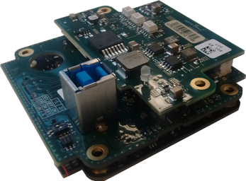
Figure 2: Boards stack
The mechanical housing is made of milled aluminum parts. The camera has a lens adapter integrating a Nikon F-mount bayonet. Thermal management is ensured by a good thermal conduction path between PCBs and housing. Also, for hot points (power converter for example), specific direct thermal path to the housing are added using thermal gap fillers.
In the software framework, the GUI and the SDK modules are built together so that the GUI is completely based on the functions provided by the SDK. The GUI is a graphic Windows application that can be used to control the connected camera through the SDK. The GUI organization is illustrated below.
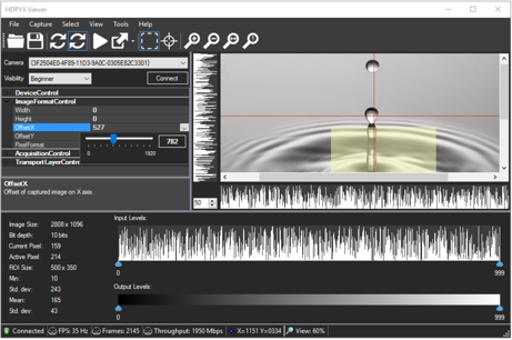
Figure 3: GUI organization